AeroWorks Extra 260 User Manual
Browse online or download User Manual for Toys & accessories AeroWorks Extra 260. 20CC _INSTALATION
- Page / 13
- Table of contents
- BOOKMARKS
Summary of Contents
1 60-90 EXTRA 260/300 DLE 20 INSTALLATION GUIDE This engine installation addendum will outline the installation of the new DLE 20cc in the 60-9
10 3. Use a 1/4” bit to drill the ignition module mounting holes. 4. Thread nylon tie through mounting holes. 5. Mount the engine ignit
11 8. Mount ignition regulator as desired. Secure all connectors with tape, safety clip or similar. Fuel Tank Installation 1. Gather the fuel
12 4. Detailed view of fuel tank stopper shown below. The Fuel “T” goes in line with the fuel line go-ing to the carburetor. The over fill line wil
13 9. Install fuel dot using the same method as described in the manual. 10. Using a rubber grommet allow the vent line to pass throu
2 3. Align mounting template with laser etched thrust lines on firewall and tape in place. 4. Use an electric drill to drill the four new motor m
3 8. Mix 5 minute epoxy in a small mixing cup and spread an even amount over two sides of the tri-stock as shown below. 9. Glue the tri-stock to
4 12. Attach the extension arm to the carb as shown below. Use blue loctite on the mounting screws to ensure they do not come loose from vibration.
5 18. Attach the short choke pushrod to the choke arm using the “Z” bend end of the pushrod as shown below. 19. Attach the throttle pushrod
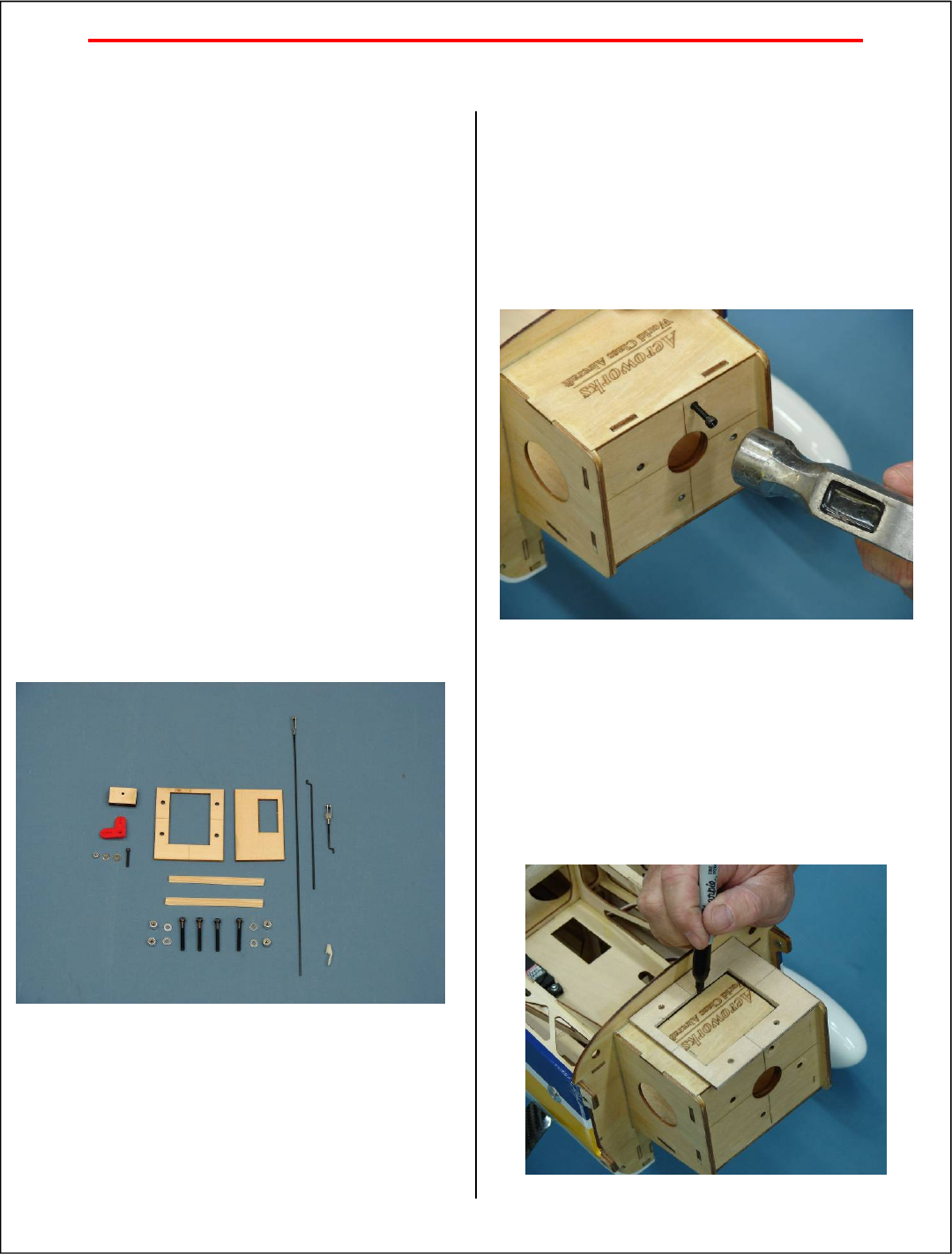
6 Choke Bell Crank Assembly 1. Gather the choke bell crank assembly parts as shown below. It is important to assemble the bell crank as shown.
7 Manual Choke Installation 1. Locate the choke bell crank that was assembled in the previous steps. Install bell crank assembly onto fuselage fl
8 5. Reinstall the short pushrod attached to the carb to the bell crank and place the bell crank mount-ing block in the fuse. Using a pencil, mark
9 2. Place the throttle servo mounting plate in the fuse as shown. It should be located on the left side of the fuse with the servo opening near th
More documents for Toys & accessories AeroWorks Extra 260


© 2020, manymanuals.com. All rights reserved. | 4.365 s |
 Manymanuals.com
 Manymanuals.de
 Manymanuals.fr
 Manymanuals.it
 Manymanuals.pl
 Manymanuals.cz
 Manymanuals.es
 Manymanuals-pt.com
Comments to this Manuals